This article is available with Ford OBD-II Trouble Codes & Ford OBD I Diagnostic Codes.
Ford OBD I Diagnostic Codes:
Full list of OBD I Diagnostic Trouble Codes for your Ford Vehicle. If your Check engine light is on you may have a serious problem. Scan your codes and follow the chart to determine what the code means. Some shops will scan your codes for free. Ford VCM2 IDS is the professional Ford Mazda diagnostic tool that will show you the trouble codes. Or do it yourself with the procedure posted below.
To read out the DTCs from the computer for diagnostic purposes, the Self Test connector is used.
Start engine and bring to normal operating temperature. If engine will not start or stalls after starting, proceed with next step.
Turn the key “OFF”, then wait ten seconds.
Activate the self test by grounding the Self-Test Input (STI) connector.
Turn the ignition key “ON”.
Record all codes received.
Turn ignition “OFF”.
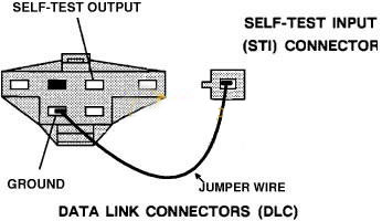
IMG 1: Data Link Connector (DLC)(Located Under hood)
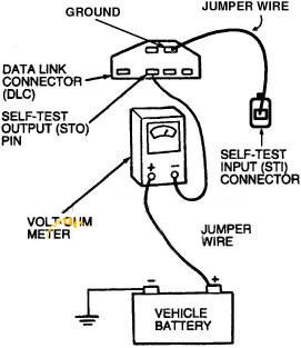
IMG 2: Analog Voltmeter Connection
Ford VCM II
11 System PASS.
12 Cannot control rpm during KOER Sell-Test high rpm check.
13 Cannot control rpm during KOER Self-Test low rpm check.
14 PIP Circuit failure.
15 PCM Read Only Memory (ROM) teat failed.
16 Rpm too low to perform H02S test.
18 SPOUT circuit open.
18 IDM circuit failure/ SPOUT circuit grounded.
19 Failure In PCM Internal voltage.
21 ECT out of Self-Test range MAP/BARO out of Self-Test range.
22 MAP/BARO out of Self-Test range.
23 TP out of Self-Test range.
24 IAT out of Self-Test range.
26 MAF out of Self-Test range.
29 Insufficient input from the Vehicle Speed Sensor (VSS).
31 EVP circuit below minimum voltage.
32 EVP voltage below closed limit.
33 EGR valve opening not detected.
34 EVP voltage above closed limit.
35 EVP circuit above maximum voltage.
41 HO2S circuit indicates system lean (right HO2S).
41 No HO2S switch detected (right HO2S).
42 HO2S circuit indicates system rich (right HO2S).
44 Secondary Air Injection system Inoperative (right side).
45 Secondary Air Injection upstream during Self-Test.
46 Secondary Air Injection not bypassed during Self-Test.
51 ECT Indicated -40 C (-40 F) /circuit open.
53 TP circuit above maximum voltage.
54 IAT Indicated -4000 (-40″F) /circuit open.
56 MAF circuit above maximum voltage.
61 ECT Indicated 123 C (254 F) / circuit grounded.
63 TP circuit below minimum voltage.
64 IAT indicated 123 C (254 F) I circuit grounded.
66 MAF circuit below minimum voltage.
67 Park/Neutral Position (PNP) switch circuit open – A/C on during Self-Test.
77 Brief WOT not sensed during Self-Test / Operator error.
79 A/C on/Defrost on during Self-Test.
81 Secondary -Air Injection Diverter (AIRD) solenoid circuit failure.
82 Secondary Air Injection Bypass (AIRS) solenoid circuit failure.
84 EGR Vacuum Regulator (EVR) circuit failure.
85 Canister Purge (CANP) circuit failure.
87 Fuel pump primary circuit failure.
91 HO2S circuit Indicates system loan (left HO2S).
91 No HO2S switch detected (left HO2S).
92 HO2S circuit indicates system rich (left HO2S).
94 Secondary Air Injection system Inoperative (left side).
95 Fuel pump secondary circuit failure.
3 Digit Ford Codes
111 System checks OK
112 (O,M) Intake Air Temperature (IAT) sensor is/was low or grounded – IAT
113 (O,M) IAT sensor is/was high or open – IAT
114 (O,R) IAT sensor out of range – IAT
116 (O,R) Engine Coolant (ECT) sensor out of range – ECT
117 (O,M) ECT sensor is/was low or grounded – ECT
118 (O,M) ECT sensor is/was high or open – ECT
121 (O,R,M) Throttle Position (TP) sensor out of range – TPS
122 (O,M) TP low (possibly grounded or open circuit) – TPS
123 (O,M) TP is/was high or short to power – TPS
124 (M) TP voltage was higher than expected – Fuel control
125 (M) TP voltage was lower than expected – Fuel control
126 (O,R,M) MAP or BARO sensor out of range – “>MAP
128 (M) MAP vacuum has not been changing – check vacuum lines – “>MAP
129 (R) No MAP or Mass Air Flow sensor change during “goose” test – MAP MAF
136 (R) Oxygen sensor not switching/system lean Left or Front HO2S – Fuel control
137 (R) Oxygen sensor not switching/system rich Left or Front HO2S – Fuel control
138 (R) Fault in Cold Start Injector circuit – Fuel control
139 (M) Oxygen sensor not switching Left or Front HO2S – Fuel control
144 (M) Oxygen sensor not switching Single, Right or Rear HO2S – Fuel control
157 (R,M) Mass Air Flow signal is/was low or grounded – MAF
158 (O,R,M) MAF sensor is/was high or short to power – MAF
159 (O,R) MAF sensor is/was out of range – MAF
167 (R) No Throttle Position sensor change in “goose” test (must get at least 25% rotation) – TPS
171 (M) Oxygen sensor not switching – system was at adaptive limits – Single, Right or Rear HO2S – Fuel control
172 (R,M) Oxygen sensor not switching – system is or was lean – Single, Right or Rear HO2S – Fuel control
173 (R,M) Oxygen sensor not switching – system is or was rich – Single, Right or Rear HO2S – Fuel control
174 (M) Oxygen sensor was slow in switching Single, Right or Rear HO2S – Fuel control
175 (M) Oxygen sensor not switching – system was at adaptive limits – Left or Front HO2S – Fuel control
176 (M) Oxygen sensor not switching – system is or was lean Left or Front HO2S – Fuel control
177 (M) Oxygen sensor not switching – system was rich Left or Front HO2S – Fuel control
178 (M) Oxygen sensor was slow in switching Left or Front HO2S – Fuel control
179 (M) Fuel system was rich at part throttle Single, Right or Rear HO2S – Fuel control
181 (M) Fuel system was lean at part throttle Single, Right or Rear HO2S – Fuel control
182 (M) Fuel system was rich at idle Single, Right or Rear HO2S – Fuel control
183 (M) Fuel system was lean at idle Single, Right or Rear HO2S – Fuel control
184 (M) Mass Air (MAF) output higher than expected – Fuel control
185 (M) Mass Air (MAF) output lower than expected – Fuel control
186 (M) Injector pulse width longer than expected or Mass Air Flow (MAF) lower than expected – Fuel control
187 Injector pulse width shorter than expected or Mass Air Flow (MAF) higher than expected – Fuel control
188 (M) Fuel system was rich at part throttle – Left or Front HO2S – Fuel control
189 (M) Fuel system was lean at part throttle – Left or Front HO2S – Fuel control
191 (M) Fuel system was rich at idle – Left or Front HO2S – Fuel control
192 (M) Fuel system was lean at idle – Left or Front HO2S – Fuel control
193 Failure in Flexible Fuel (FF) sensor circuit – Fuel control
194 (M) Perform cylinder balance test to check for inoperative injectors
195 (M) Perform cylinder balance test to check for inoperative injectors
211 (M) Ignition PIP signal was erratic or missing – Ignition Systems
212 (M) Ignition TACH signal was erratic (module/wiring) or SPOUT circuit fault – Ignition Systems
213 (R) Ignition SPOUT or SAW circuit open or shorted – Ignition Systems
214 (M) Error in Cylinder ID (CID) circuit or signal – Ignition Systems
215 (M) Primary circuit failure – ignition coil 1 – Ignition Systems
216 (M) Primary circuit failure – ignition coil 2 – Ignition Systems
217 (M) Primary circuit failure – ignition coil 3 – Ignition Systems
218 (M) IDM signal open or high or left coil pack failure – Ignition Systems
219 (M) SPOUT circuit failure, timing defaulted to 10 degrees – follow code 213 diagnosis
222 (M) IDM open or high or right coil pack failure – Ignition Systems
223 (M) Dual Plug (DPI), SPOUT or IDM circuit fault – Ignition Systems
224 (M) Failure in ignition coil primary circuit – Ignition Systems
225 (R) Knock sensor not tested (ignore if not pinging) – KS
226 (O) Ignition Diagnostic Monitor (IDM) signal fault – Ignition Systems
232 (M) EI primary coil circuit failure – Ignition Systems
238 (M) EI primary circuit failure – ignition coil 4 – Ignition Systems
311 (R) AIR system not working – Single, Right or Rear HO2S – Air Injection
312 (R) AIR not diverting – Air Injection
313 (R) AIR not bypassing – Air Injection
314 (R) AIR inoperative, Left or Front HO2S – Air Injection
326 (R,M) Pressure Feedback EGR shows low pressure EGR not seating or not seating intermittantly – PFE
327 (O,R,M) EGR feedback signal is/was low – EVR or PFE
328 (O,R,M) EGR Valve Position (EVP) is/was low – EVR
332 (R,M) EGR did not open/respond during test or if memory code, did not open intermittantly – EVR or PFE
334 (O,R,M) EVP sensor is/was high – EVR
335 (O) EGR feedback signal is/was out of range – EVR or PFE
336 (O,R,M) PFE sensor signal is/was was high – “>PFE
337 (O,R,M) EGR feedback signal is/was was high – EVR
338 (M) Cooling system did not heat up (check cooling system / thermostat operation)
339 (M) Cooling system overheated (check cooling system / thermostat operation)
341 (O) Octane jumper installed (information only code to notify you if it is installed)
411 (R) Idle speed system not controlling idle properly (generally idle too high) – ISC
412 (R) Idle speed system not controlling idle properly (generally idle too low) – ISC
452 (M) Vehicle Speed Sensor (VSS) problem
511 (O) No power to PCM pin 1 or bad PCM (processor)
512 (M) Memory power (PCM pin 1) was interrupted – Was battery disconnected ?
513 (O) Replace processor (PCM) (internal failure)
519 (O) PSP switch/circuit open – PSP h Pedal Position (CPP) circuit fault – PNP
528 (M) System shows voltage at pin 10 (is A/C on ?) or pin 30 (PNP, CPP switch) – PNP
529 (M) Data Communications Link to processor failure Service any EEC codes, erase memory and retest If code is still present refer to instrument cluster diagnosis manual
533 (M) Data Communications Link to instrument cluster failure – see 529
536 (O,R,M) Brake On Off open or shorted to ground – BOO
538 (R) System did not receive “goose” test – TESTS
539 (O) System shows voltage at PCM pin 10 Is A/C on ?
542 (O,M) Fuel pump open, bad ground or always on – – Power / Fuel Pump Circuits
543 (O) Fuel pump monitor circuit shows no power – Power / Fuel Pump Circuits
(M) (Service 556 code first if present) Fuel pump relay or battery power feed was open – Power / Fuel Pump Circuits
551 Problem in Intake Manifold Runner Control (IMRC) solenoid/circuit – Solenoids
552 (O) AIRB solenoid/circuit failure – Solenoids
553 (O) AIRD solenoid/circuit failure – Solenoids
554 (O) Fuel Press Regulator Control solenoid/circuit fault – Power / Fuel Pump Circuits
556 (O,M) Fuel pump relay primary circuit fault – Power / Fuel Pump Circuits
557 (O,M) Low speed pump relay primary circuit fault – Power / Fuel Pump Circuits
558 (O) EGR vacuum regulator solenoid/circuit failure – EVR or PFE or Solenoids
559 (O) A/C relay primary circuit fault – A/C and Fan Circuits
563 (O) High Fan Control (HFC) circuit failure – A/C and Fan Circuits
564 (O) Fan Control (FC) circuit failure – A/C and Fan Circuits
565 (O) Canister Purge 1 solenoid/circuit failure – Solenoids
566 (O) transmission 3/4 shift solenoid/circuit – Transmissions
569 (O) Canister Purge 2 solenoid/circuit failure – Solenoids
578 (M) A/C pressure sensor VREF short to ground – A/C and Fan Circuits
579 (M) ACP sensor did not change with A/C on – A/C and Fan Circuits
581 (M) Cooling fan current was excessive – A/C and Fan Circuits
582 (O) Open cooling fan circuit – A/C and Fan Circuits
583 (M) Fuel pump current was excessive – Power / Fuel Pump Circuits
584 (M) Open power ground circuit – Power / Fuel Pump Circuits
585 (M) A/C clutch current was excessive – A/C and Fan Circuits
586 (M) Open circuit in A/C clutch – A/C and Fan Circuits
587 (O, M) Communication problem between PCM and Variable Control Relay Module (VCRM) – Power / Fuel Pump Circuits
617 (M) Transmission shift failure (1/2 shift) – Transmissions
618 (M) Transmission shift failure (2/3 shift) – Transmissions
619 (M) Transmission shift failure (3/4 shift) – Transmissions
621 (O) Solenoid/circuit failure – shift solenoid 1 – Transmissions
622 (O) Solenoid/circuit failure – shift solenoid 2 – Transmissions
624 (O,M) Solenoid/circuit failure -Electronic Pressure Control (EPC) current is high – Transmissions
625 (O,M) Solenoid/circuit failure – Electronic Pressure Control (EPC) current is low – Transmissions
626 (O) Transmission Coast Clutch (CCS) Solenoid/circuit fault – Transmissions
627 (O) Torque Converter Clutch circuit fault – Transmissions
628 (M) Excessive converter clutch slippage – Transmissions
629 (O,M) Torque Converter Clutch circuit fault – Transmissions
631 (O) Overdrive Cancel Light circuit problem – Transmissions
632 (R) E4OD – Transmission Control Switch (TCS) should be cycled once between engine ID and Goose test
633 (O) 4x4L switch should be in 4×2 or 4×4 high for the test
634 (O,M) Park/Neutral Position (PNP) or Clutch Pedal Position (CPP) circuit fault Electronic shift transmission – Manual Lever Position (MLP) sensor out of range in Park-Transmissions
636 (O,R) Transmission Oil Temperature (TOT) sensor out of range – Transmissions
637 (O,M) TOT sensor is/was high or open – Transmissions
638 (O,M) TOT sensor is/was low or grounded – Transmissions
639 (R,M) Transmission Speed sensor (TSS) circuit fault – Transmissions
641 (O) Transmission solenoid/circuit failure Shift Solenoid 3 – Transmissions
643 (O,M) Torque Converter Clutch (TCC) circuit – Transmissions
645 (M) Transmission 1st gear failure – Transmissions
646 (M) Transmission 2nd gear failure – Transmissions
647 (M) Transmission 3rd gear failure – Transmissions
648 (M) Transmission 4th gear failure – Transmissions
649 (M) Transmission EPC system failure – Transmissions
651 (M) Transmission EPC solenoid/circuit fault – Transmissions
652 (O) Torque Converter Clutch (TCC) circuit fault – Transmissions
654 (O) Transmission selector not in PARK – Transmissions
656 (M) Torque Converter Clutch (TCC) slip – Transmissions
657 (M) Transmission temperature was excessive – Transmissions
Leave a Reply