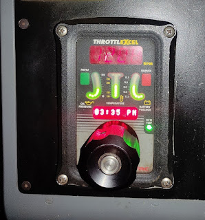
Remote Throttle
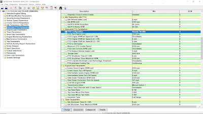
1). Use CAT ET to Check the Programming of the Parameter Dedicated PTO Parameters.
→Connect CAT ET to the data link connector.
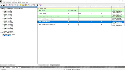
→Access the Dedicated PTO Parameters on Cat ET. Note the programming of the parameter PTO Configuration (Remote Throttle).
2). Check the Circuit for the PTO On/Off Switch.
→Activate the PTO operation.
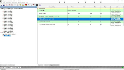
→Access the CAT ET Status screens that display the following Status parameters. Read More: Status Tool on Caterpillar ET Software.
PTO Config (Remote Throttle)
PTO On/Off Switch – J1/P1:56
→Verify that each of the interlocks for the PTO are set. Then, while the CAT ET Status screen is being monitored, move the PTO On/Off Switch to the ON and OFF position.
3). A Remote Accelerator Pedal Position Sensor is connected to ECM P1/J1-68 (Input 8) when the PTO
Configuration is programmed to Remote Throttle.
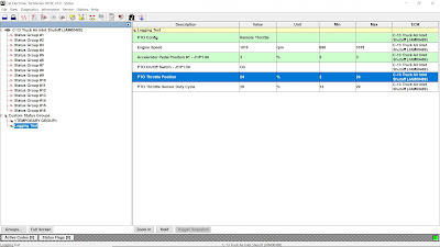
→Monitor the Status of PTO Throttle Position and PTO Throttle Sensor Duty Cycle and output to controls the Engine Speed.
→Or you can manually measure the PTO Remote Throttle signal using the Multimeter (DC Volts and Duty Cycle).
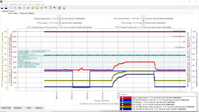
4). Monitor using the Real Time Graphing while simulate the PTO Configuration Test (Remote Throttle). Read More: Real Time Graphing using Caterpillar ET Software.
When the PTO Configuration is programmed to Remote Switches or to Remote Throttle and the PTO On/Off Switch is On, the following circuits are ignored:
• Service Brake Pedal Position Switch 1
• Service Brake Pedal Position Switch 2
• Clutch Pedal Position Switch
• Neutral Switch
• Accelerator Pedal Position Sensor
• Cruise Control Set/Resume Switch that is located in the Cab.

Leave a Reply